
Partial denture design
A removable partial denture is a mechanical system supported by teeth, mucosa or both. Start with the support pattern, then explain how each rest, connector and clasp contributes to a maintainable design.
Quick revision summary
Design a support system
Kennedy class describes the pattern of spaces, while rests, base extension and connector rigidity determine support and movement. Select clasps only after analysing how the prosthesis will behave under load.
Survey anatomy before prescribing
Choose an insertion path, guide surfaces and useful undercuts while checking soft-tissue clearance. RPI, RPA, bars and plates have indications and limitations; a component name is not a universal design.
Plan for long-term use
Make the appliance cleansable and acceptable, provide a complete prescription and check the framework before tooth setup. Review tissue response, fit and movement, especially as distal-extension ridges change.
Common mistake
A clasp retains the denture against removal. It cannot compensate for absent support, a flexible connector or an extension base that has lost its adaptation.
Partial denture design
A removable partial denture is a mechanical system supported by teeth, mucosa or both. Start with the support pattern, then explain how each rest, connector and clasp contributes to a maintainable design.
Start with the patient and the remaining teeth
Record the patient’s functional and aesthetic priorities, the teeth they wish to replace, their experience of previous dentures and their ability to clean and handle a prosthesis. Replacing every absent tooth is not always necessary. Consider a shortened dental arch, fixed options or no replacement when the remaining dentition meets the patient’s needs. An acrylic transitional denture and a definitive metal framework have different purposes and design constraints.
Chart caries, periodontal support, mobility, restorability, vitality where relevant, occlusion and available interarch space. Inspect the ridge, mucosal quality, sulcus and undercuts. A visually attractive cast cannot establish abutment prognosis. Stabilise active disease and decide which teeth will remain before finalising the design.
Kennedy classification describes the support problem
Classify after planned extractions that affect the arch. The most posterior relevant space determines the class. Additional separate spaces are counted as modifications, rather than by the number of absent teeth. Teeth that will not be replaced, such as an absent third molar, do not automatically create another saddle. Classification is a description, not a complete laboratory prescription.
| Class | Distribution of spaces | Design implication |
|---|---|---|
| I | Bilateral posterior edentulous areas extending behind the remaining teeth | Both distal-extension bases can rotate under load; plan tooth–mucosal support and control of lifting. |
| II | A unilateral posterior edentulous area extending behind the remaining teeth | Asymmetric support and rotation require a cross-arch design. |
| III | A bounded edentulous area with teeth anterior and posterior to it | Support can usually be derived from abutments at both ends of the saddle. |
| IV | One anterior edentulous area crossing the midline, anterior to the remaining teeth | Appearance and the lever effect of the anterior saddle need attention; this class has no modifications. |
Kennedy classes I–IV, original open-license schematic

Original SVG declared own work by Hans Meine, using licensed Kaligula tooth outlines. Classification concept cites Kennedy’s 1932 text; this is a modern digital drawing, not a textbook scan. Shows basic classes without modification spaces or framework designs. Roman-numeral labels retained; do not imply a connector prescription from class alone.
Kennedy classes I–IV, original open-license schematic · Hans Meine; tooth artwork based on Kaligula (CC BY-SA 3.0) · CC BY-SA 4.0. None; original SVG downloaded. Tooth outlines: Kaligula, CC BY-SA 3.0.
The components and the job each must do
| Component | Mechanical role | How to examine it |
|---|---|---|
| Rest and rest seat | Support against movement towards the tissues and a defined load pathway to the tooth | Check shape, seating, material clearance and whether preparation has created a useful supporting surface. |
| Saddle / denture base | Carries artificial teeth and distributes load to the ridge where required | Assess extension, adaptation, tissue quality and the need for future relining. |
| Major connector | Unites the arch rigidly so components work together | Check rigidity, tissue clearance, comfort, hygiene and anatomical constraints. |
| Minor connector / proximal plate | Connects rests and saddles, and contributes to guidance and bracing | Check contact with the planned guiding surfaces and compatibility with the insertion path. |
| Retentive clasp arm | Engages a selected undercut to resist displacement away from the foundation | Assess the terminal location, approach, flexibility and retention during removal. |
| Reciprocal or bracing component | Opposes lateral force as the retentive arm flexes; contributes to stability | Confirm contact at the relevant time rather than assuming any lingual metal is reciprocal. |
| Indirect retainer | Uses a supported component away from the fulcrum to resist lifting of an extension base | Locate it relative to the anticipated rotation axis and assess the quality of its support. |
Surveying: decide the insertion path before choosing undercuts
Survey a diagnostic cast or appropriately prepared digital model to identify guiding surfaces, heights of contour, usable undercuts and interferences. A survey line describes the tooth relative to the selected path; it is not a permanent anatomical line. Changing the tilt alters the apparent undercuts and may solve one problem while creating another.
Use an undercut gauge and match the selected undercut to clasp material, length, cross-section and design. A flexible wrought-wire arm and a cast arm do not behave identically. Record the chosen path so it can be reproduced. Plan tooth modification conservatively: guiding planes, rest seats and selected contour changes should have a defined role. Where a surveyed crown is genuinely indicated, incorporate the planned rest, guide plane and retentive contour into its prescription.
Maxillary major connectors: compare geometry and support
Connector names alone do not specify thickness, dimensions or stiffness. An anteroposterior bar in a published model is not interchangeable with every anteroposterior strap design. Examine the actual outline shown in the reference image.
| Connector | Useful features | Constraints and cautions |
|---|---|---|
| Palatal strap | A broad, relatively thin connector can provide rigidity without a bulky narrow bar | Select width, outline and tissue relationship for the actual saddles and palate. |
| Anteroposterior connector | Separated anterior and posterior elements joined laterally can create a rigid configuration | Consider tongue tolerance, palatal anatomy, rugae and the design of the connecting elements. |
| Palatal plate / more extensive palatal coverage | Can increase palatal contribution to support where tooth support is limited | Greater coverage affects comfort and hygiene; define the clinical benefit. |
| Horseshoe / U-shaped connector | May be considered where anatomy or an anterior arrangement limits alternatives | Open geometry is more liable to flex; it is not the default because it appears to cover less palate. |
Palatal strap and anteroposterior bar framework designs
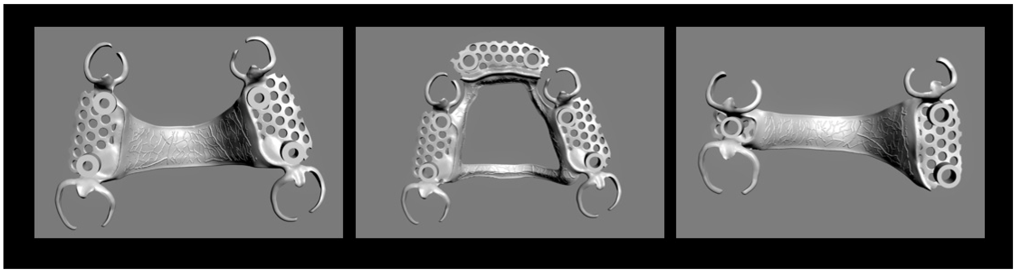
Original Figure 3 from a Co-Cr laboratory study. Left and middle use tooth-supported Kennedy III configurations; right uses a Kennedy II configuration. Source names left/right connectors palatal straps and middle anteroposterior bar. These are CAD designs without teeth or mucosa, not clinical photographs or prescriptions.
Palatal strap and anteroposterior bar framework designs · Stefan Rues; Akinori Tasaka; Isabella Fleckenstein; Shuichiro Yamashita; Peter Rammelsberg; Sophia Boehm; Franz Sebastian Schwindling · CC BY 4.0. None; high-resolution original publisher figure downloaded. Original publication.
Mandibular connectors: floor-of-mouth anatomy matters
Measure the functional sulcus clinically, with the tongue and floor of the mouth moving. A cast captured at rest may exaggerate the space available for a bar. The teaching models illustrate connector form; they do not establish a safe clearance for an individual patient.
| Connector | When it may be considered | What must be checked |
|---|---|---|
| Lingual bar | Adequate functional space between the gingival margins and the elevated floor of the mouth | A sufficiently rigid bar and safe gingival/tissue clearance must fit without impingement. |
| Lingual plate | Functional space limits a bar, or selected tooth/support circumstances favour a plate | Rest support, contact, hygiene access and periodontal status; a plate does not automatically splint diseased teeth successfully. |
| Other connector designs | Unusual anatomy or tooth inclinations may make standard lingual options unsuitable | Use a case-specific specialist plan rather than defaulting to a bulky or uncomfortable substitute. |
Lingual bar on a mandibular teaching model
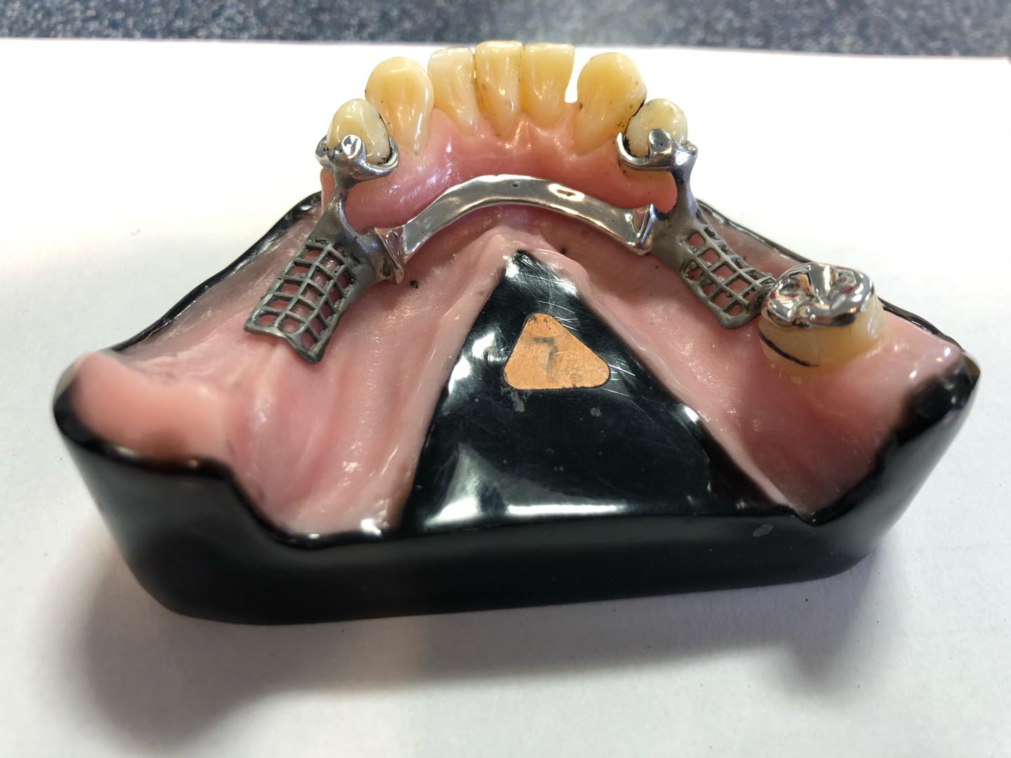
Actual photographed teaching framework from Dundee Dental School. The bar lies below the lingual surfaces of the anterior teeth. Posterior saddle meshwork and clasp/rest assemblies are visible; one side includes a remaining posterior tooth and the other a free-end ridge. Alloy, exact dimensions, clinical suitability and formal Kennedy classification are not documented by the source.
Lingual bar on a mandibular teaching model · MookieSutida · CC BY-SA 4.0. None; original photograph downloaded.
Lingual plate on a mandibular teaching model
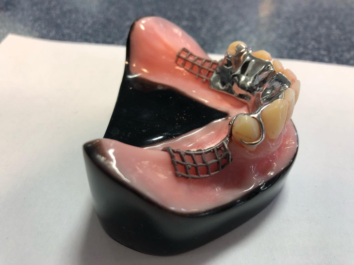
Actual photographed Dundee Dental School teaching framework. The lingual plate extends onto the lingual surfaces of the remaining teeth, unlike the separate lingual bar image. Bilateral posterior free-end ridges and meshwork are visible. This shows connector coverage, not a universal prescription; source does not verify Co-Cr alloy or dimensions.
Lingual plate on a mandibular teaching model · MookieSutida · CC BY-SA 4.0. None; original photograph downloaded.
Clasp assemblies: retention needs support and reciprocation
An I-bar approach may be obstructed by a shallow vestibule, a high frenum or a soft-tissue undercut. Do not use the RPI acronym as a substitute for surveying. If the proximal plate or clasp binds during saddle movement, the intended stress-release behaviour may be lost.
| Assembly | What it includes | Design reasoning |
|---|---|---|
| Circumferential / Akers | An occlusally approaching retentive arm with rest and reciprocal/bracing elements | Often useful for suitable tooth-supported saddles; assess the surveyed undercut and insertion path. |
| RPI | Mesial Rest, distal Proximal plate and gingivally approaching I-bar | In suitable distal-extension cases, the geometry aims to permit release as the saddle rotates tissuewards, reducing harmful torque. |
| RPA | Mesial Rest, Proximal plate and a suitable Akers-type arm | An alternative when an I-bar approach is unsuitable; its releasing behaviour depends on correct geometry. |
| Wrought-wire combination | A flexible wire retentive element combined with suitable cast support/bracing | Flexibility may be useful, but wire form, undercut, durability and adjustment still require planning. |
Buccal circumferential clasp arm and clasp pattern
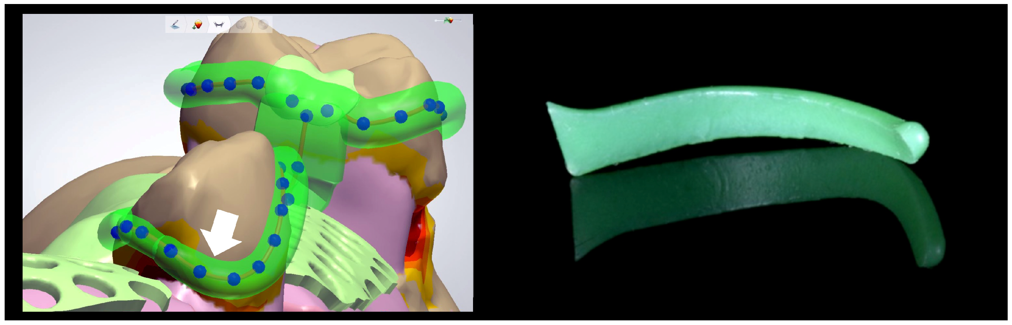
Original Figure 4. Left shows a buccal retentive clasp tip designed into a 0.25 mm undercut; right shows the preformed wax-pattern shape used as a comparison. Useful for circumferential clasp geometry. It does not separately label a reciprocal arm or demonstrate simultaneous reciprocation during insertion.
Buccal circumferential clasp arm and clasp pattern · Stefan Rues; Akinori Tasaka; Isabella Fleckenstein; Shuichiro Yamashita; Peter Rammelsberg; Sophia Boehm; Franz Sebastian Schwindling · CC BY 4.0. None; high-resolution original publisher figure downloaded. Original publication.
RPI clasp design, buccal and lingual views
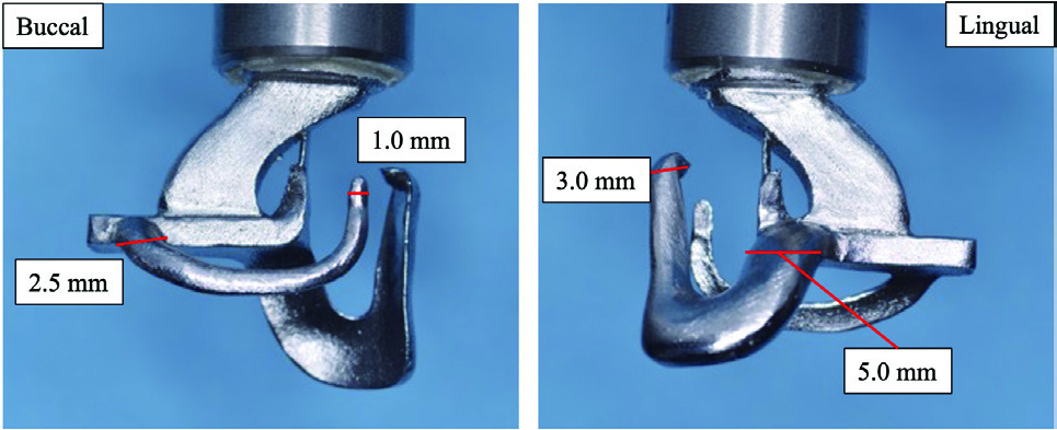
Original Figure 2: detached RPI test specimen, showing the approach arm and clasp framework from both sides. Original dimensional labels preserved. The large upper arm connects to testing machinery; dimensions describe this experiment, not general clinical requirements.
RPI clasp design, buccal and lingual views · Yuki Uekubo; Yoshimitsu Kato; Keita Tomono; Mitsuo Kato; Juro Wadachi; Shinji Takemoto; Shuichiro Yamashita · CC BY 4.0. Embedded Figure 2 JPEG extracted unchanged from original PDF; figure caption is supplied in metadata. Original publication.
RPI clasp on a prepared simulated abutment
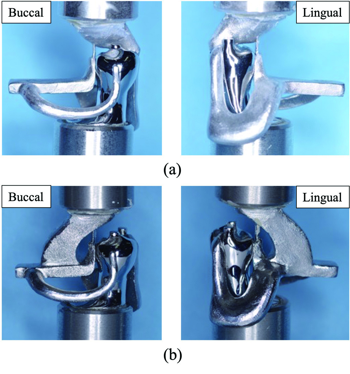
Original Figure 4: assembly seated on a simulated mandibular right second premolar. Paper describes a mesial rest, distal guide plane/proximal plate and I-bar. Panels a and b are different testing connections, not different clinical indications. Metallic teeth, upper fixtures and extensions belong to the test apparatus.
RPI clasp on a prepared simulated abutment · Yuki Uekubo; Yoshimitsu Kato; Keita Tomono; Mitsuo Kato; Juro Wadachi; Shinji Takemoto; Shuichiro Yamashita · CC BY 4.0. Embedded Figure 4 JPEG extracted unchanged from original PDF; all original labels preserved. Original publication.
Distal-extension mechanics and indirect retention
In a bounded saddle, support is mainly from teeth at its ends. In a distal-extension saddle, the mucosa under the base compresses more than the periodontal support of an abutment. The base can rotate tissuewards under chewing and lift in the opposite direction with sticky food or displacing forces. The actual movement depends on several components; a simplified fulcrum line is a way to reason about it, not a claim that the denture behaves as a perfect hinge.
Place effective indirect support sufficiently away from the relevant rotation axis, with a rigid connection and a properly seated rest. Its effectiveness depends on both lever distance and support quality. Extend the base appropriately to distribute load without interfering with function. An impression or altered-cast strategy may be considered for selected extension cases; it is not required for every partial denture and does not replace sound framework design.
Worked designs: explain the choices before naming a clasp
These are educational starting patterns. They are not prescriptions for a real patient. The photographs and study models below show actual component arrangements, which may differ from the assumptions in a worked example. Use the figure’s own caption to distinguish the published design from the hypothetical case.
| Example arch | Reasoned starting design | What could change it |
|---|---|---|
| Mandibular bilateral distal extensions: Kennedy I | Appropriately extended posterior bases, rigid cross-arch connector, mesial rests on suitable terminal abutments, compatible releasing clasp assemblies and supported indirect retention anterior to the main fulcrum | Functional lingual space, tissue undercuts, abutment tilt, periodontal support, aesthetics and opposite-arch loading. |
| Maxillary unilateral distal extension plus a bounded space: Kennedy II modification 1 | A rigid maxillary connector joining the saddles; support at the bounded space and a planned tooth–mucosal support strategy for the extension; retention and indirect support based on the surveyed arch | Palatal anatomy, available teeth, saddle length and the position of usable undercuts. |
| Maxillary bounded posterior space: Kennedy III | Rests on suitable abutments at both ends, a rigid connector, appropriately positioned retention and reciprocal/bracing components | A weak posterior abutment, limited occlusal space or an incompatible insertion path may alter the plan. |
| Anterior space crossing the midline: Kennedy IV | Supported anterior replacement, adequate connector rigidity and a considered retention arrangement that balances appearance and control of rotation | Smile line, ridge loss, phonetics, tooth contours and aesthetic tolerance of visible components. |
Maxillary metal framework with an anteroposterior palatal connector
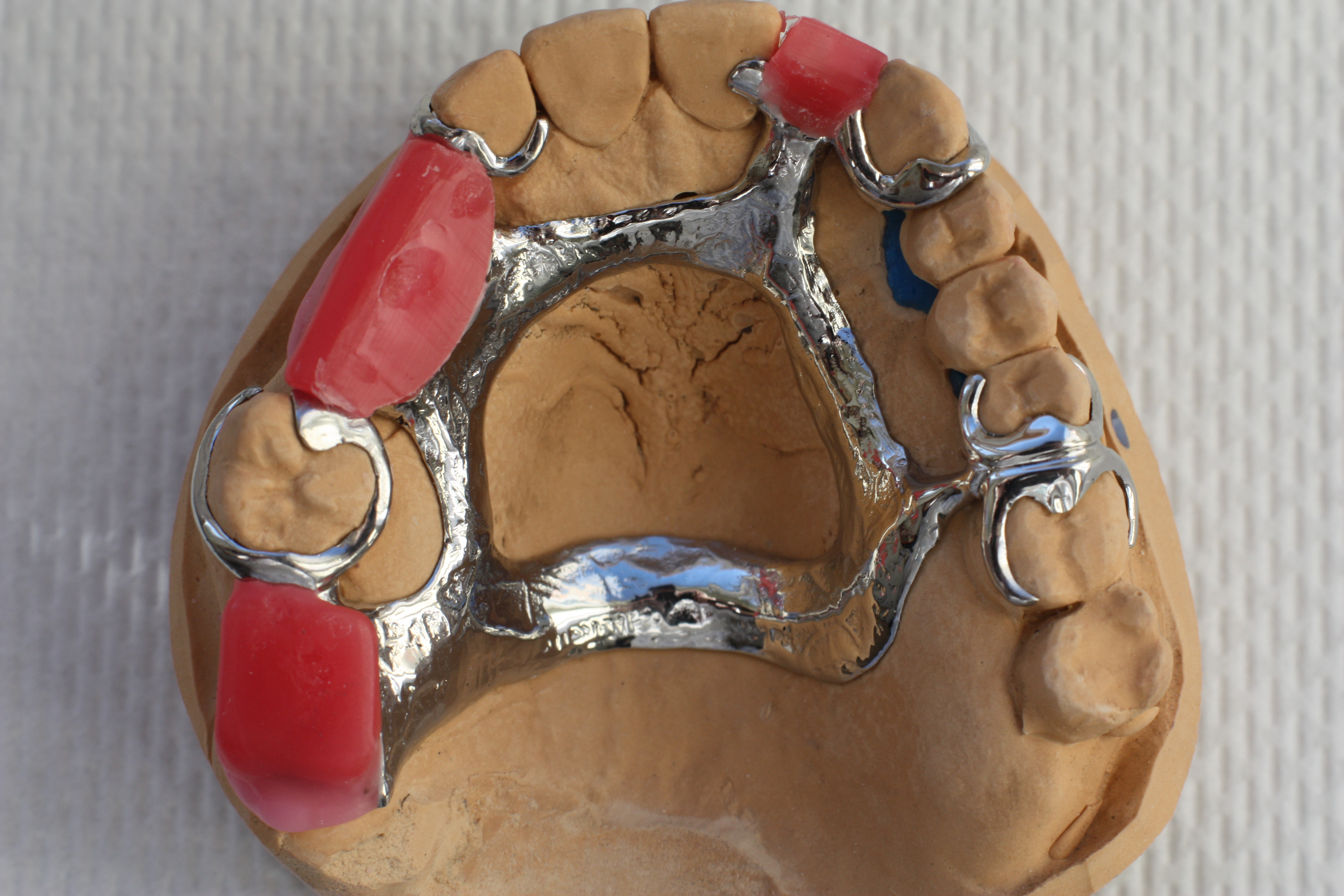
Actual maxillary cast framework on a working model. Anterior and posterior palatal elements surround an open central area; tooth-bounded saddle spaces and tooth support are visible. Pink material represents a laboratory stage, not a completed denture base. Exact bar-versus-strap dimensions, alloy composition and patient-specific prescription are not supplied by the source.
Maxillary metal framework with an anteroposterior palatal connector · Sterilgutassistentin · CC BY-SA 3.0. None; original photograph downloaded.
Communicate a complete laboratory prescription
Identify the teeth and saddles to replace, the chosen insertion path, connector outline, rest positions, clasp material and undercuts, guide-plane/proximal-plate relationships, acrylic retention and any surveyed restorations. Provide the casts or files and the clinical constraints. Collaborate with the technician over fabrication feasibility, but retain responsibility for the clinical design.
At framework try-in, check that rests seat fully and the framework fits passively along the intended path. Verify guide-plane contacts, tissue clearance and the timing of reciprocation. A framework forced into place may look seated while stressing teeth. Resolve a seating discrepancy before recording the bite or adding teeth. At delivery, check the processed base, occlusion, insertion/removal and accessible cleaning around every component.
Follow-up: test the design in use
Review pain, rocking, clasp damage, food trapping, plaque and changes in abutment or ridge support. A loose denture may need more than tightening a clasp: loss of base adaptation can increase rotation and load the terminal teeth. Evaluate the whole mechanism before altering retention. Inspect rest seats and proximal surfaces for caries and the gingiva for inflammation.
Teach cleaning of the denture and remaining teeth, including the surfaces hidden by plates and clasps. Plan maintenance and explain that an extension base may need relining as the ridge changes. If an abutment is lost, reassess the new support pattern and repair options rather than adding a tooth automatically to an unchanged framework.
A distinction to remember
A clasp retains the denture against removal. It cannot compensate for absent support, a flexible connector or an extension base that has lost its adaptation.
A mandibular bilateral distal-extension denture rotates under chewing. Which design features need review?
Reveal the reasoning
Review base extension and fit, terminal abutment rests, clasp release behaviour, indirect retention, connector rigidity and occlusal contacts. Teeth and mucosa displace differently. The cause may require a coordinated redesign rather than simply tightening clasps or adding another retentive arm.
Guidance to read alongside this chapter
Test your recall
What are the four main Kennedy classes?
Show answer
Class I is bilateral distal extension, II unilateral distal extension, III a bounded space and IV one anterior space crossing the midline. Classify after planned extractions. The classification describes the support pattern but does not determine the complete design or every component.