
Radiographic anatomy
Location and expected continuity help distinguish structures from disease.
Quick revision summary
Trace normal landmarks and recognise variation
Trace the mandibular canal and mental foramina, cortical borders, maxillary sinus floor, nasal structures and other visible landmarks according to the image type. Projection and superimposition can alter their apparent position.
Relate dark and bright areas to anatomy
Air spaces and foramina can produce radiolucent appearances; cortical boundaries often form radiopaque lines. Trace a structure through its expected course rather than identifying it from one isolated patch.
Use effects on structures as diagnostic clues
Displacement, interruption of a cortical outline, root resorption or altered canal position can suggest that a finding is more than normal variation. Describe these effects without assuming that one sign provides a histological diagnosis.
Common mistake
A radiolucency near an apex is not automatically endodontic disease, and an anatomical label should not conceal unexplained change.
Recognise normal anatomy before labelling pathology
Location and expected continuity help distinguish structures from disease.
Trace normal landmarks and recognise variation
Trace the mandibular canal and mental foramina, cortical borders, maxillary sinus floor, nasal structures and other visible landmarks according to the image type. Projection and superimposition can alter their apparent position. A mental foramen near a premolar apex may resemble a periapical radiolucency; clinical tests, lamina dura and suitable alternative views help resolve the distinction.
Normal anatomy varies, and a named landmark is not an explanation for every nearby change. Assess borders, symmetry, displacement, root effects and continuity with the expected structure. Compare suitable previous images and the clinical findings. Avoid assigning a definitive histological diagnosis from an image alone. A report can describe a reliable radiographic pattern while keeping the differential and uncertainty explicit.
Lateral cephalogram: orient the orthodontic record
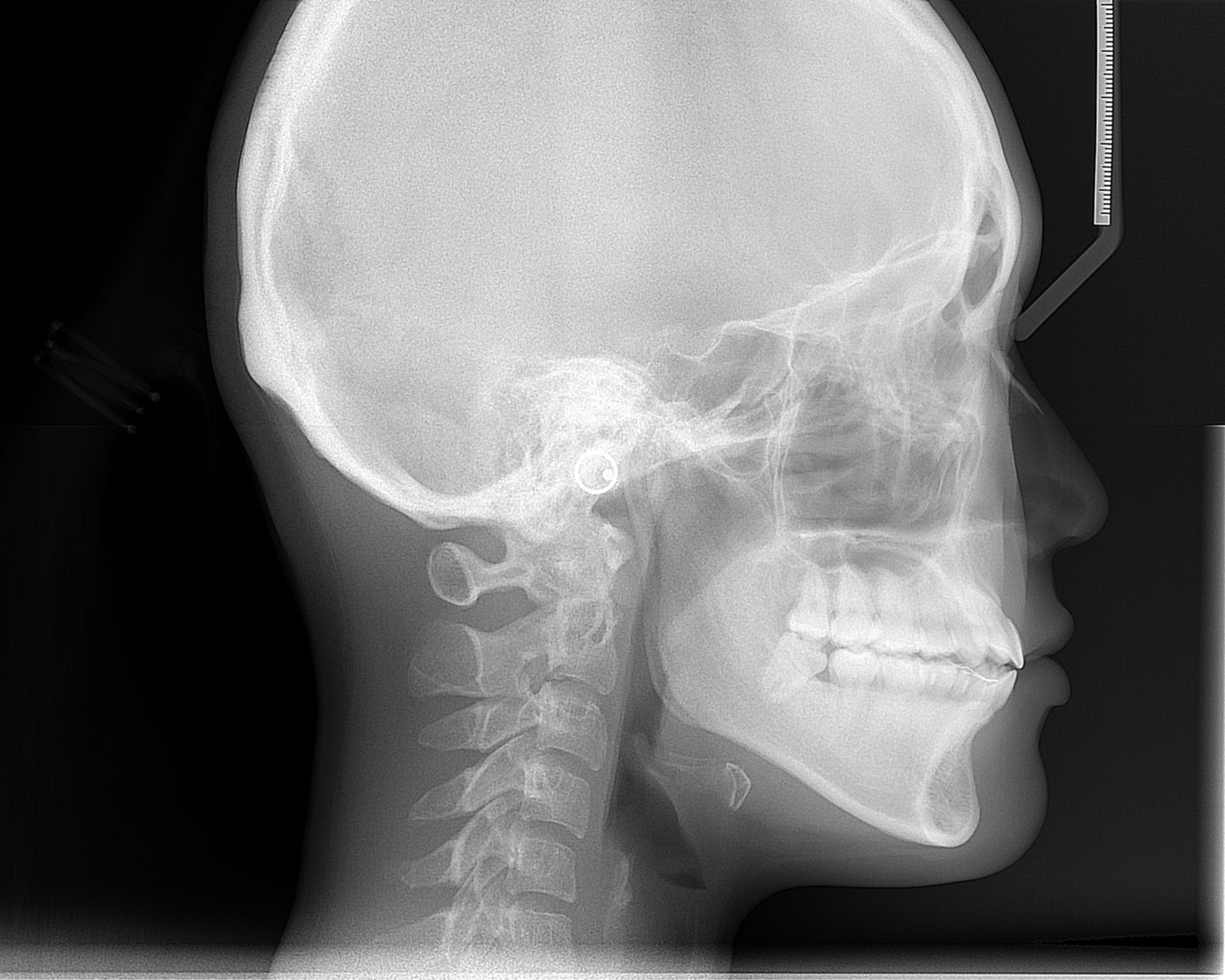
Orient the cranial base, jaws, incisors and soft-tissue outline. Use this as an anatomy example alongside the chapter on justification and interpretation of orthodontic records.
Cephalometric radiograph.JPG · ANUG · CC BY-SA 4.0. Image reproduced without alteration; original marks and any embedded credits retained.
Mandibular landmarks
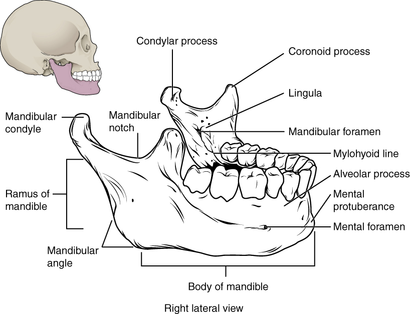
Locate the mental and mandibular foramina, lingula and mylohyoid line. The mandibular foramen, lingula and mylohyoid line are medial landmarks; this schematic brings several surfaces together. Relate the landmarks to nerve risk and fracture assessment.
Mandibular landmarks · OpenStax College · CC BY 3.0. Original image; displayed at a responsive size. Original publication.
Key distinctions in practice
| Finding or option | What it means | Clinical consequence |
|---|---|---|
| Mental foramen | Normal opening near the premolar region | Correlate with pulp tests and root support. |
| Mandibular canal | Course of the neurovascular canal | Trace continuity and relationship to the proposed procedure. |
| Maxillary sinus | A normal air-containing structure | Assess its boundary and the relevant clinical context. |
| Lamina dura / ligament space | Supporting structures around roots | Assess changes together with symptoms and tests. |
Panoramic anatomy with unerupted third molars
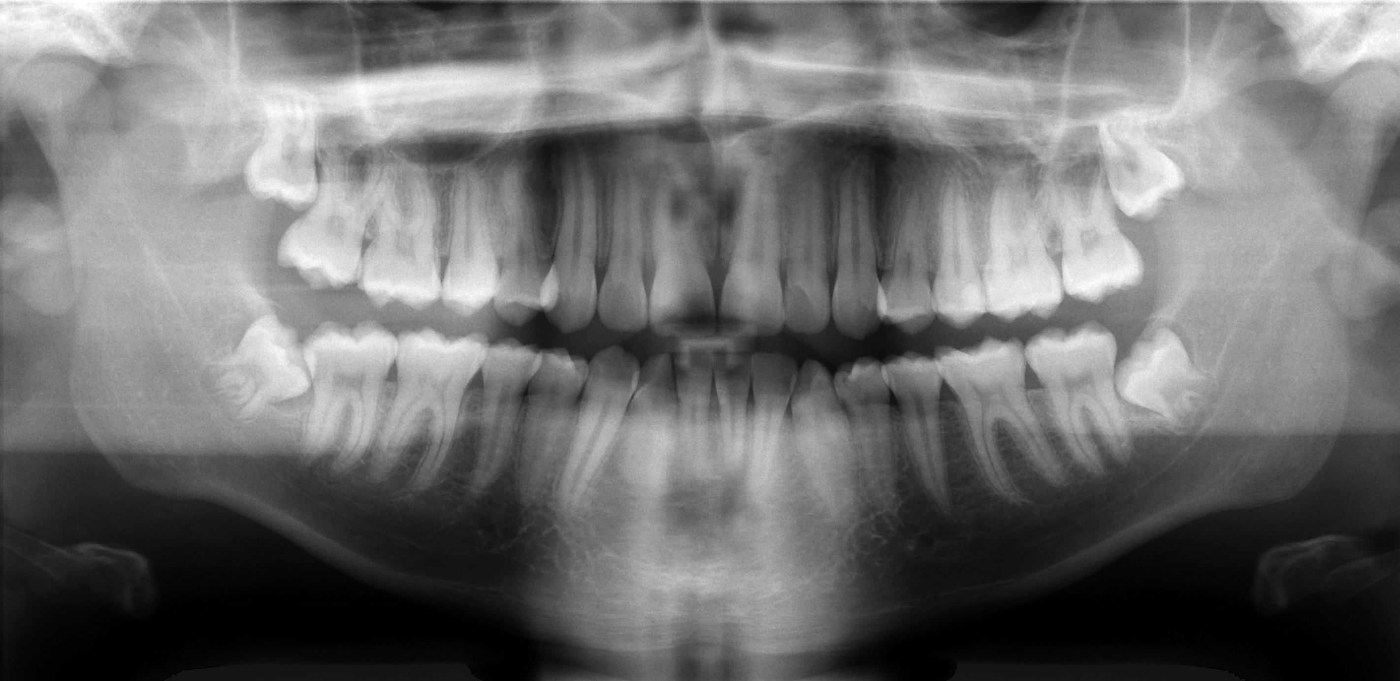
Scan the whole image systematically: compare both sides, trace the mandibular borders and canals, inspect the maxillary sinuses and count the teeth. This published example includes unerupted third molars; it is not an all-normal reference. Radiographic overlap alone cannot establish the three-dimensional nerve–root relationship.
Basic panoramic radiograph.jpg · Coronation Dental Specialty Group · CC BY 3.0. None; original image reproduced without alteration.
Can a panoramic image alone prove whether roots touch the inferior alveolar nerve?
No. It is a two-dimensional projection. Interpret the signs in clinical context, and request further imaging only when justified by a management question.
Relate dark and bright areas to anatomy
Air spaces and foramina can produce radiolucent appearances; cortical boundaries often form radiopaque lines. Trace a structure through its expected course rather than identifying it from one isolated patch. The mandibular canal, mental foramen, incisive region, sinus floor and nasal boundaries have characteristic relationships, but individual anatomy and projection vary.
For a premolar-apical radiolucency, assess the root, lamina dura, clinical pulp findings and the expected position of the mental foramen. A different justified projection may help resolve superimposition. Do not treat a healthy tooth merely because a normal opening is projected near its apex. Equally, an expected landmark should not be used to dismiss a new or changing abnormality without assessment.
Mixed dentition on a panoramic radiograph
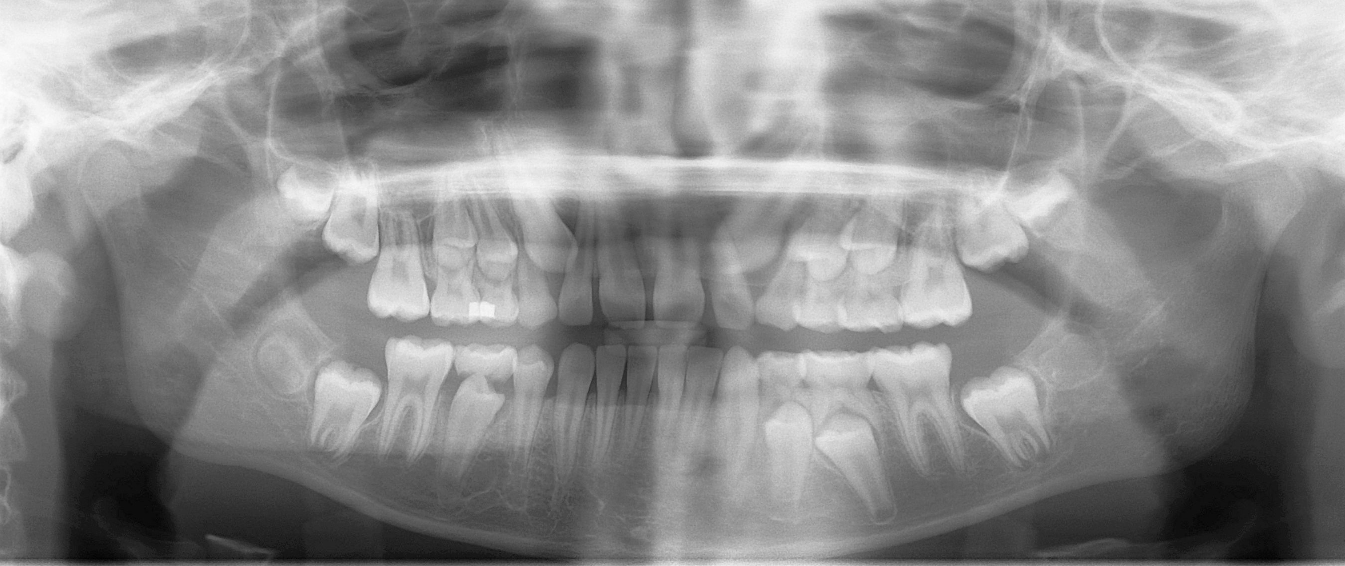
Distinguish erupted permanent teeth, retained primary teeth and unerupted successors. Compare development on the two sides and account for every permanent tooth. This is one published example of mixed dentition, not a fixed age-based template for every child.
Mixed dentition pan.jpg · Coronation Dental Specialty Group · CC BY 3.0. None; original image reproduced without alteration.
Which permanent teeth erupt without replacing primary teeth?
The permanent molars. Premolars replace the primary molars; permanent incisors and canines replace their primary predecessors.
Use effects on structures as diagnostic clues
Displacement, interruption of a cortical outline, root resorption or altered canal position can suggest that a finding is more than normal variation. Describe these effects without assuming that one sign provides a histological diagnosis. Comparison with suitable previous images can establish whether a feature is stable, although lack of an earlier image is not evidence of recent onset.
Reference diagrams show an idealised layout. Real images may have missing teeth, altered anatomy, asymmetry, restoration artefacts or surgical change. Use them to orient the search, then return to the actual image and clinical question. If the distinction remains uncertain, seek appropriate reporting advice rather than assigning a confident label to an unexplained shadow.
Nasopalatine duct cyst: an anterior maxillary example
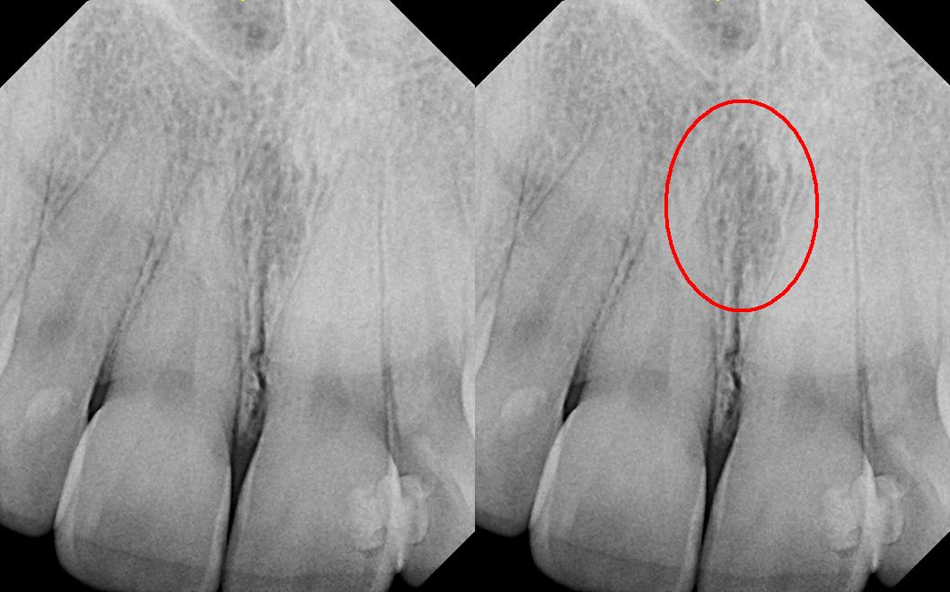
The right panel repeats the image with the source’s red circle highlighting the midline region. The source explicitly corrects its filename: this is reported as a nasopalatine duct cyst, not a nasolabial cyst. Consider the incisive canal and adjacent incisors, including pulp tests. The subtle appearance illustrates why a labelled example is not a stand-alone diagnostic rule.
Nasolabial_duct_cyst.JPG · DRosenbach · CC BY-SA 3.0. Source image reproduced without alteration; any arrows or circles are part of the original.
Why assess the adjacent incisors before treating a midline anterior maxillary radiolucency as endodontic disease?
A nasopalatine duct cyst or normal incisive-canal anatomy may overlap the incisor roots. Clinical examination, pulp tests and appropriate imaging help avoid unnecessary endodontic treatment of otherwise healthy teeth.
Stafne bone cavity: panoramic location
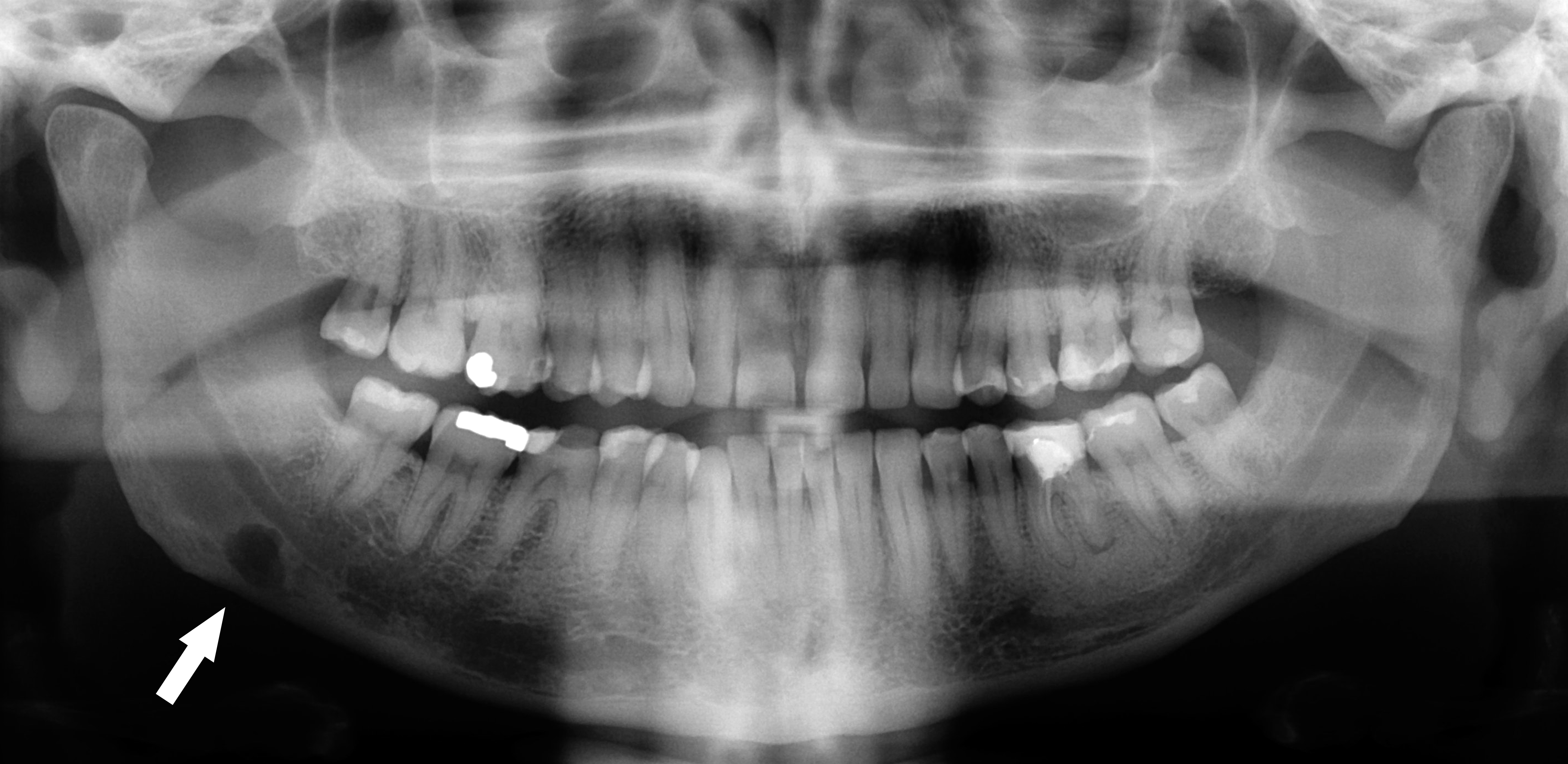
Follow the original arrow to the rounded radiolucency near the lower border of the right mandible, on the left of the displayed image. The source identifies a Stafne defect. Compare its position below the mandibular canal with the tooth-related relationships of odontogenic cysts. The axial CT shows the same source case from another plane.
Stafne defect panorex.jpg · Coronation Dental Specialty Group · CC BY 3.0. Reproduced without alteration. Labels, arrows and circles, where present, belong to the source image.
Which anatomical relationship is particularly helpful in this example?
Its location below the mandibular canal near the posterior lower border. Use the full pattern and clinical context; that relationship alone is not a universal rule for every radiolucency.
A distinction to remember
A radiolucency near an apex is not automatically endodontic disease, and an anatomical label should not conceal unexplained change.
A radiolucency lies near a vital mandibular premolar apex. What should you consider before diagnosing apical disease?
Reveal the reasoning
Normal mental-foramen projection, test reliability, lamina dura and other views or findings. Location alone does not establish an endodontic lesion.
Guidance to read alongside this chapter
Test your recall
Why can a mental foramen mimic a lesion?
Show answer
It may project near the apex of a premolar.